Introduction
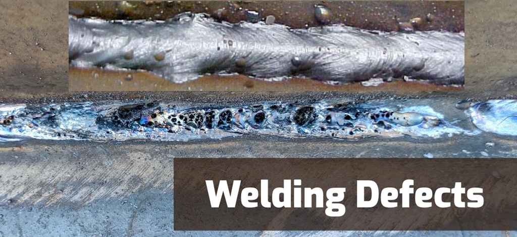
Welding defects are imperfections in welded joints that compromise their strength, integrity, or appearance. These flaws can arise from improper technique, unsuitable parameters, or poor preparation. Identifying and mitigating them is essential for structural safety and product longevity.
Classification of Welding Defects
Welding defects are generally categorized by their location:
-
External defects appear on the weld surface and are often visible to the naked eye.
-
Internal defects lie within the weld metal or heat‐affected zone and require non‐destructive testing (NDT) techniques for detection.
Table of Most Common Welding Defects
| No. | Defect | Category |
|---|---|---|
| 1 | Porosity | External & Internal |
| 2 | Cracks | External & Internal |
| 3 | Lack of Fusion | Internal |
| 4 | Incomplete Penetration | Internal |
| 5 | Slag Inclusion | Internal |
| 6 | Undercut | External |
| 7 | Overlap | External |
| 8 | Burn‐through | External |
| 9 | Excessive Reinforcement | External |
| 10 | Underfill | External |
| 11 | Spatter | External |
| 12 | Crater Formation | External |
| 13 | Distortion | Structural |
| 14 | Concavity | External |
| 15 | Convexity | External |
| 16 | Mechanical Damage | External |
Detailed Descriptions, Causes, and Remedies
1. Porosity
Porosity manifests as small gas pockets or voids trapped in the solidified weld metal. It weakens the joint by reducing cross‐sectional area and can lead to premature failure if severe. Causes:
-
Moisture or oil on base metal or filler.
-
Excessive shielding gas turbulence.
Remedies:
-
Thoroughly clean and dry all surfaces before welding.
-
Optimize gas flow rate and nozzle position.
2. Cracks
Weld cracks are linear separations in the bead or heat‐affected zone. They are critical defects that act as stress concentrators and can propagate under load. Causes:
-
Rapid cooling or high restraint stress.
-
Hydrogen embrittlement from moisture.
Remedies:
-
Preheat thick sections to slow cooling.
-
Use low‐hydrogen electrodes and control moisture.
3. Lack of Fusion
This internal defect occurs when the weld metal fails to merge completely with the base metal or previous weld pass. It forms weak interfaces that compromise strength. Causes:
-
Insufficient heat input or incorrect torch angle.
-
Too fast travel speed.
Remedies:
-
Increase current or voltage within weld procedure limits.
-
Adjust torch angle to improve access.
4. Incomplete Penetration
Incomplete penetration is the failure of the weld to extend through the joint thickness. It reduces the effective cross‐section and bearing capacity of the weld. Causes:
-
Inadequate root opening or low heat input.
-
Improper joint fit‐up.
Remedies:
-
Ensure proper joint preparation and root gap.
-
Raise current or slow travel speed to achieve full penetration.
5. Slag Inclusion
Slag inclusion refers to non‐metallic solid material trapped within the weld metal. It creates stress risers and can lead to crack initiation. Causes:
-
Inadequate slag removal between passes.
-
Improper electrode manipulation.
Remedies:
-
Chip and wire‐brush each pass before depositing the next layer.
-
Maintain correct electrode angle to let slag escape.
6. Undercut
Undercut is a groove melted into the base metal adjacent to the weld toe. It reduces the weld’s cross‐section and acts as a crack initiation point. Causes:
-
Excessive heat input or slow travel speed.
-
Incorrect torch angle.
Remedies:
-
Lower amperage or increase travel speed.
-
Optimize torch angle and manipulation.
7. Overlap
Overlap happens when the weld metal flows over the base metal without fusing to it. It forms a weak shoulder and can trap contaminants. Causes:
-
Low heat input or excessive filler deposition.
-
Slow travel speed.
Remedies:
-
Increase heat input or travel speed.
-
Control filler feed to match base metal capacity.
8. Burn‐through
Burn‐through occurs when excessive heat melts completely through thin workpieces. It compromises joint integrity and causes holes. Causes:
-
High current or low travel speed on thin material.
-
Poor heat control.
Remedies:
-
Reduce amperage or increase welding speed.
-
Back‐purge or use backing strips on very thin sheets.
9. Excessive Reinforcement
This defect is characterized by a weld bead protruding above the desired contour, leading to stress concentrations. Causes:
-
Overfeeding filler or low travel speed.
Remedies:
-
Balance filler feed rate and travel speed.
-
Trim or grind excessive bead before service.
10. Underfill
Underfill describes a weld bead that is below the base metal surface, creating a weakened cross‐section. Causes:
-
Insufficient filler or low heat input.
Remedies:
-
Increase filler feed or heat input within procedure tolerances.
11. Spatter
Spatter consists of small droplets of molten metal expelled from the arc that adhere to surrounding surfaces. It detracts from appearance and can cause porosity if entrapped. Causes:
-
High arc voltage or incorrect polarity.
-
Excessive contact tip‐to‐work distance.
Remedies:
-
Optimize voltage and polarity settings.
-
Maintain correct torch-to-work distance.
12. Crater Formation
A crater forms at the end of a weld due to abrupt arc termination, creating a concave depression that can crack. Causes:
-
Failure to fill the crater before stopping the arc.
Remedies:
-
Employ crater‐fill cycle or backing technique.
-
Slowly withdraw the electrode while reducing current.
13. Distortion
Distortion is the warping or twisting of welded assemblies due to non‐uniform thermal expansion and contraction. Causes:
-
High heat input in concentrated areas.
-
Inadequate fixturing.
Remedies:
-
Sequence welds symmetrically and use tack welds.
-
Apply clamps and pre‐load components.
14. Concavity
Concavity occurs when the weld face is sunken relative to the surrounding base metal. It can signal low heat input or insufficient filler. Causes:
-
Low current or rapid travel speed.
Remedies:
-
Increase heat input or slow travel speed.
-
Adjust electrode angle to deposit metal evenly.
15. Convexity
Convexity is a pronounced bulge on the weld face, leading to stress concentrations. Causes:
-
Excessive filler deposition or low travel speed.
Remedies:
-
Balance filler feed and travel speed.
-
Grind bead to desired profile if necessary.
16. Mechanical Damage
Mechanical damage includes gouges, dents, or scratches on the welded joint caused by handling or fabrication tools. These imperfections act as stress risers. Causes:
-
Improper handling or use of power tools near weld zones.
Remedies:
-
Protect welds during post‐weld operations.
-
Repair damage by grinding and re‐welding if needed.
Non‐Destructive Testing Methods
-
Visual Testing (VT) for surface flaws.
-
Dye Penetrant Testing (PT) for fine cracks.
-
Magnetic Particle Testing (MT) for ferrous materials.
-
Ultrasonic Testing (UT) for subsurface inclusions and cracks.
-
Radiographic Testing (RT) for volumetric inspection.
Frequently Asked Questions
-
Why does porosity occur despite using shielding gas? Moisture in the electrode, poor nozzle coverage, or turbulent gas flow can introduce gas into the weld pool.
-
How can I distinguish between surface and subsurface cracks? Surface cracks are visible; subsurface cracks require UT or RT for detection.
-
What is the ideal preheat temperature? It depends on material thickness and composition, but common practice ranges from 100°C to 200°C for carbon steels.
-
How do I prevent undercut in TIG welding? Reduce current, increase travel speed, and maintain a slight forehand angle of about 5 - 15°.
-
When should I use backing bars or strips? On thin sections prone to burn‐through or when full penetration without backing is difficult.
-
Can excessive reinforcement ever be beneficial? Only when post‐weld machining is required to achieve precise dimensions; otherwise it’s undesirable.
-
How tight should my joint fit-up be to avoid incomplete penetration? Follow weld procedure specification guidelines - typically a root gap of 1 - 2mm for most groove welds.
-
Does spatter affect weld strength? It doesn’t directly affect the weld metal but can cause stress risers and hinder inspection.
-
How often should I calibrate welding equipment? At least annually, or whenever performance drift is detected.
-
What standards govern acceptable defect limits? ISO 6520 for classification, ISO 5817 and ISO 10042 for acceptance levels.
Shop for welding machines from trusted brands at qtetech.com and qtetech.com/en. QTE Technologies is a proud global MRO provider, serving customers in over 180 countries and dedicated to ensuring a complete and satisfying customer experience. Established in 2010, we offer over 1 million products across all industries and engineering disciplines. Additionally, you can reach us anytime via 24 x 7 chat support, phone, WhatsApp or email. Discover what our valued customers have to say about our services on our dedicated review page.
Article Author: QTE Technologies Editorial Team (with a strong background in both engineering and innovation - over 15 years of experience).