1. Introduction
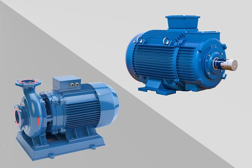
The pump and the motor are two fundamental devices in fluid handling and mechanical power transmission systems.
Although they often work together, each performs a distinct function: the motor converts energy into mechanical motion, while the pump uses that motion to move fluids.
This article delves into every technical aspect—definitions, operating principles, design, performance, applications, maintenance, selection criteria, and a case study—to clarify their differences and synergies.
2. Definitions
2.1 Motor
-
A device that converts electrical, chemical, or thermal energy into mechanical motion (rotational or linear).
-
Common types include:
-
AC motors (squirrel-cage induction, synchronous)
-
DC motors (brush-type, brushless)
-
Internal combustion engines (gasoline, diesel)
-
2.2 Pump
-
A machine that imparts mechanical energy to a fluid, creating flow (discharge) and pressure.
-
Major classifications:
3. Operating Principles
3.1 Motor Operation
-
In an electric motor, current in windings generates a rotating magnetic field, producing torque on the rotor.
-
In an internal combustion engine, fuel–air combustion in cylinders creates expanding gases that move pistons, converting chemical energy to mechanical rotation through a crankshaft.
3.2 Pump Operation
-
Centrifugal pump: the impeller spins, generating centrifugal force that accelerates fluid from the eye to the periphery, increasing pressure and flow.
-
Reciprocating pump: a piston or plunger moves back and forth in a cylinder, creating low pressure (suction) on intake and high pressure on discharge.
-
Rotary vane pump: sliding vanes trap fluid in compartments and transfer it from inlet to outlet under pressure.
4. Design and Components
| Component Category | Motor | Pump |
|---|---|---|
| Static parts | Stator core, windings, housing | Casing, bearing housing, seal chamber |
| Rotating parts | Rotor (squirrel-cage, wound), shaft, fan | Shaft, impeller/rotor, pistons or vanes |
| Sealing & bearings | Shaft seals, ball or roller bearings | Mechanical seals, packing glands, plain bearings |
| Cooling system | Forced air, liquid jacket, heat sink fins | Fluid recirculation, external cooling jackets |
| Power transmission | Direct coupling, belt/gear drives | Same as motor plus coupling to impeller or piston rod |
| Parameter | Motor | Pump |
|---|---|---|
| Rated output | Power (kW, HP) | Flow rate (Q, m³/h or gpm) and head (H, m or ft) |
| Efficiency (η) | 85–98% for modern electric motors | 50–90% depending on pump type and size |
| Characteristic curve | Torque vs. speed (T–ω) | Head vs. flow (H–Q) |
| Starting requirements | High inrush current for AC; variable control for DC | Must match motor torque to avoid stall or cavitation |
| Environmental sensitivities | Ambient temperature, humidity, altitude | Fluid viscosity, temperature, solids content |
6. Applications
-
Motor applications
-
Pump applications
-
Water supply and wastewater treatment
-
Hydraulic power units and lubrication systems
-
Chemical injection, fuel transfer, and vacuum service
-
7.1 Motor Maintenance
-
Periodic insulation resistance testing and winding inspections
-
Bearing lubrication or replacement; fan and ventilation cleaning
-
Brush replacement (for brushed DC motors) and commutator polishing
7.2 Pump Maintenance
-
Seal and packing inspection; mechanical seal replacement as needed
-
Impeller, vane, or piston wear checks; clearance adjustments
-
Strainer and filter cleaning to prevent clogging and cavitation
-
Determine required fluid flow rate Q and pressure head H.
-
Select pump whose H–Q curve intersects the operating point within its best efficiency region.
-
Calculate hydraulic power:
P_\text{pump} = \frac{1000\;\text{kg/m}^3 \times 9.81\;\text{m/s}^2 \times 60\;\text{m}^3\!/\text{h} \times 120\;\text{m}}{0.75 \times 3600 \times 1000} \approx 26\;\text{kW} $$
Select a centrifugal pump rated at 70 m head and 60 m³/h, driven by a 30 kW, 1450 rpm induction motor with VFD control for soft start and energy optimization.
9. Conclusion
Motors and pumps serve complementary roles: the motor produces mechanical power, and the pump transforms that power to move fluids.
Understanding their distinct principles, designs, and performance parameters is essential to optimize efficiency, reliability, and lifecycle costs in industrial and building services systems.